SOSEN provides rich user guides to help you solve frequently asked questions quickly in your business

CLASS 2:
Derived from the North American UL 1310 standard, Class 2 refers to power supply devices with inherently safe outputs. These devices must be isolated from the input and meet the following basic electrical performance requirements for single-channel outputs:
1.Voltage:
·DC voltage ≤ 60V in dry or damp environments (≤ 42.4V in Canada).
·DC voltage ≤ 30V in wet environments.
2.Power: Total output power < 100W.
3.Current:
·Rated output current ≤ 5A.
·Maximum current during overload ≤ 8A.
4.Compliance with UL 1310 abnormal test requirements.
CLASSⅡ:
Derived from IEC standards or equivalent, ClassⅡ refers to the insulation structure or type of a product for electric shock protection. This means the product’s protection against electric shock relies not only on basic insulation but also on additional safety measures, such as double insulation or reinforced insulation, without grounding or reliance on installation conditions.
·If the product is designed for standalone use (external to luminaires), it is fully classified as ClassⅡ and marked with the double-square symbol “□□”.
·If it is only for built-in use (inside luminaires), it is marked with the double-circle symbol “◎”.
Key Differences:
·CLASS 2 (UL standard) focuses on reducing risks of electric shock or fire at the output.
·CLASSⅡ (IEC standard) emphasizes safety against electric shock at the input.
Note: Both are pronounced "class two."

LED Power Supply: Function and Classification
What is an LED Power Supply?
Due to the characteristics of LED beads (which can only be driven by direct current), an integrated circuit is required between the mains power supply and the LED luminaire to convert alternating current (AC) to direct current (DC) (as shown in the diagram above). This integrated circuit is called an LED control driver, commonly known as an LED power supply (LED Driver).
Functions of an LED Driver:
1.Converts AC to DC.
2.Supplies the required current magnitude and voltage range for the luminaire.
3.Provides circuit safety protection for the luminaire.
4.Performs electromagnetic compatibility (EMC) processing and filtering.
5.Enables additional smart controls, etc.
Classification by Output Type:
·Constant Current Driver: Output current remains constant, while the output voltage varies within a specific range depending on the load resistance.
Example: DC 27–42V, 1000mA.
·Constant Voltage Driver: Output voltage is fixed, while the output current varies with load changes.
Example: DC 24V, 0–1250mA.
Classification by Isolation Method:
·Isolated Power Supply:
Conversion process: Electrical → Magnetic → Electrical.
Uses a transformer to step down high voltage to a lower voltage, which is then rectified into DC output.
·Non-Isolated Power Supply:
Conversion process: Electrical → Electrical.
Uses inductors and other components to step down high voltage before rectifying it into DC output.
Comparison:
·Isolated Power Supply Topology (as shown in the diagram above).
·Non-Isolated Power Supply Topology (as shown in the diagram above).
Classification by Installation Location:
·Built-in Power Supply: Integrated into the luminaire housing. If the luminaire has a metal casing, insulation measures must be applied between the power supply and the lamp cavity.
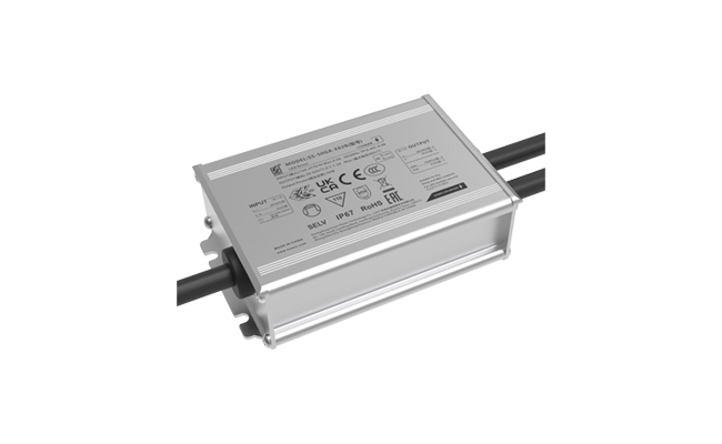
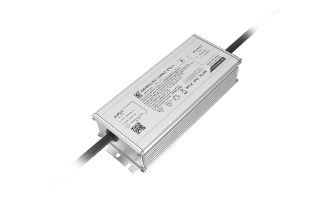
·External Power Supply: Placed outside the luminaire, optionally fixed. Requires an insulated housing, and for outdoor use, waterproof potting is necessary.
Class I/II/III Luminaires
Class I Luminaire:
·Relies on basic insulation for electric shock protection.
·Exposed conductive parts are grounded, ensuring that accessible conductive parts remain non-energized even if basic insulation fails.
Class II Luminaire:
·Relies on double insulation or reinforced insulation for safety, with no grounding required.
·Provides protection through two layers of insulation (basic + supplementary) or equivalent reinforced insulation.
Class III Luminaire:
·Operates using Safety Extra-Low Voltage (SELV) (≤50V AC or ≤120V DC).
·SELV power is isolated from high voltage via an isolating transformer, and grounding is not permitted.
Class I/II Drivers
Class I Drivers (Independent/Built-in with Grounding):
·AC Input: 3-pin (L, N, PE – Protective Earth).
·Design Requirements:
·Protective earth is connected to prevent electric shock.
·Basic insulation (creepage distance >2.5 mm) between protective earth and other circuits.
·Ground Impedance Test: 25A/1 minute between grounding conductor and touchable parts.
·Terminology:
·Independent Class I Driver: Standalone driver with grounding.
·Built-in Class I Driver: Integrated into the luminaire, with grounding.
Class II Drivers (Independent/Built-in without Grounding):
1.AC Input: 3-pin (L, N, FE – Functional Earth for EMC purposes):
·Functional earth is used for EMI suppression, not for safety.
·Reinforced insulation (creepage distance >5.0 mm) between functional earth and other circuits.
Terminology:
·Independent Class II Driver: Standalone driver with functional earth.
·Built-in Class II Driver: Integrated into the luminaire, without grounding.
2. AC Input: 2-pin (L, N):
·Reinforced insulation (creepage distance >5.0 mm) between primary live parts and touchable surfaces.
·Regional Requirements:
·Europe/China: Creepage distance >2.5 mm for built-in drivers.
·Australia: Creepage distance >5.0 mm for built-in drivers.
·Terminology:
·Independent Class II Driver: Standalone driver with 2-pin input.
·Built-in Class II Driver: Integrated into the luminaire, without grounding.
Driver-Luminaire Compatibility
1. Class I Drivers (Independent/Built-in with Grounding):
·Applicable to: Class I luminaires only.
·Reason: Basic insulation requires grounding for safety.
2. Class II Drivers (Independent/Built-in without Grounding):
·Applicable to: Class I and Class II luminaires.
·Wiring:
·For Class I luminaires: Connect L/N to driver input; ground wire to luminaire chassis.
·For Class II luminaires: Connect L/N to driver input (no grounding required).
Lightning Surge Immunity Test Standard: IEC 61000-4-5,
The test levels are as follows:
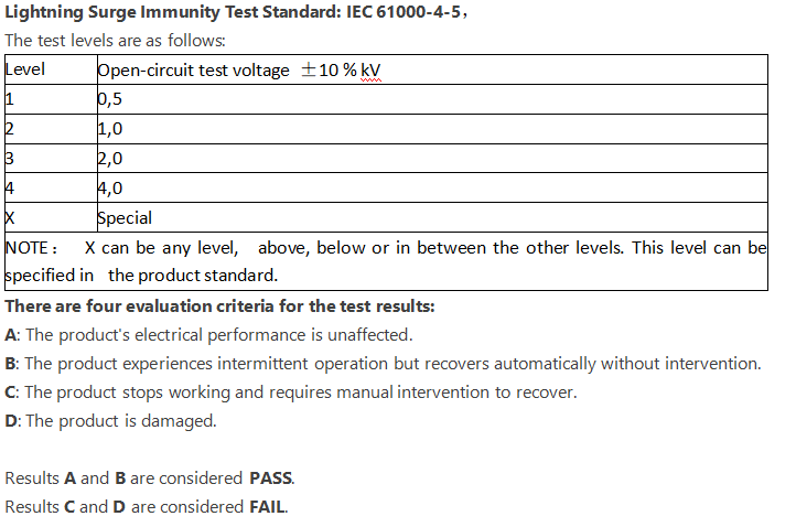
There are four evaluation criteria for the test results:
A: The product's electrical performance is unaffected.
B: The product experiences intermittent operation but recovers automatically without intervention.
C: The product stops working and requires manual intervention to recover.
D: The product is damaged.
Results A and B are considered PASS.
Results C and D are considered FAIL.
Because safety testing organizations apply a tolerance of ±10% based on the given operating voltage range, the actual test ranges for the above four voltage ranges are:
Our company conducts reliability testing for power supplies based on these ranges to ensure proper operation within the specified working voltage range.
The protection (IP) rating of a power supply is expressed as IPxy, where x represents the dust protection level (ranging from 1 to 6), and y represents the water protection level (ranging from 1 to 8).
Below are the testing methods for various water protection levels:
IPX1 - Method Name: Vertical Drip Water Test
a) Test Equipment: Drip water testing device
b) Sample Placement: Place the sample in its normal working position on a rotating sample table rotating at 1 rpm, with the distance from the top of the sample to the drip nozzle not exceeding 200mm.
Test Conditions: Drip rate of 10 ± 0.5 mm/min
c) Test Duration: 10 minutes
IPX2 - Method Name: 15° Tilt Drip Water Test
a) Test Equipment: Drip water testing device
b) Sample Placement: Position the sample so that one surface forms a 15° angle with the vertical line, with the distance from the top of the sample to the drip nozzle not exceeding 200mm. After testing one surface, rotate to test the next surface, repeating four times in total.
c) Test Conditions: Drip rate of 30 ± 0.5 mm/min
Test Duration: 4 × 2.5 minutes (total 10 minutes)
IPX3 - Method Name: Spray Water Test
a) Test Method: Swing pipe spray water test
Test Equipment: Swing pipe water splash test device
Sample Placement: The sample is placed in such a way that the surface is exposed to the swing pipe, with an appropriate radius of the swing. The sample table height should be within the swing pipe's direct range...
| Standard | Determine the level | Four judgment levels |
IEC/EN61000-4-5 |
Criterion B (Common mode 10kV, Differential mode 6kV) Coupling resistance (Common mode 12 ohms, Differential mode 2 ohms) |
The test results are evaluated according to four criteria: Class A: No electrical impact. Class B: Occasional intermittent operation, but automatically recovers. Class C: Stops working, but can recover after power is turned off and restarted. Class D: Damage。 |
| ANSI/C82.77-5-2017 (Outdoor lighting/UFO) |
Criterion B (Common mode 6kV, Differential mode 6kV) Coupling resistance (Common mode 2 ohms, Differential mode 2 ohms) |
|
IEC/EN 61000-4-5 |
Criterion B (Common mode 6kV, Differential mode 4kV) Coupling resistance (Common mode 12 ohms, Differential mode 2 ohms) |
|
IEC/EN 61000-4-5 |
Criterion B (Common mode 4kV, Differential mode 4kV) Coupling resistance (Common mode 12 ohms, Differential mode 2 ohms) |
The wattage of LED fixtures commonly referred to by LED lighting manufacturers refers to the total input power of the fixture. This value can vary significantly due to the efficiency differences of the internal power supply under different operating conditions. The wattage of the power supply referred to by power supply manufacturers refers to the maximum output power of the power supply. The relationship between the two can be expressed by the following formula:
Fixture total power × Power supply efficiency = Power supply output power.
The safety shell temperature of a product refers to the highest operating shell temperature at a specified location that is allowed by safety certifications, without considering the long-term lifespan of the product. The warranty shell temperature refers to the maximum operating shell temperature of the power supply, which is specified to ensure the product can operate reliably and stably within the warranty period.
To assess whether a power supply can be used for making flicker-free lighting fixtures, check the size of the output ripple current. If the ripple current is less than 10%, the lighting fixture can be flicker-free. If it is between 10% and 20%, the fixture will have low-frequency flicker. If the ripple current exceeds 20% to 100%, the power supply can only be used for making lighting fixtures with visible flicker.